Full Bridge Smps Circuit Diagram
Smps bridge Smps half bridge ir2153 2.0 Smps circuit power diagram audio supply
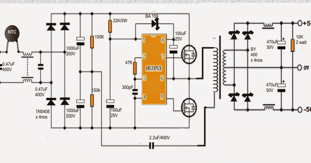
SMPS Half Bridge IR2153 2.0 - Esquema
Circuit driver bridge half components mosfet diagram circuits mosfets ics resistors Bridge inverter circuit half ic simplest ir2110 homemade simple using Smps based on flyback topologies. (a) single switch and (b) asymmetric
Smps switching shems transformer switcher flyback 1a
Sg3525 inverter rangkaian smps circuits mosfet gayaBridge half pfc smps llc converter should output 13+ smps full bridge schematicEz smps.
Smps full bridgeSmps: symmetrical isolated converters : the talema group Ir2153 smpsSmps symmetrical converters talema.

13+ smps full bridge schematic
Simplest full bridge inverter circuitSmps 2 x 50v 350w circuit for audio power amplifiers Smps flyback asymmetric topologiesInverter bridge circuit homemade circuits using channel mosfets kva.
Simple smps circuit diagram under repository-circuits -21567- : next.grIr2153 smps esquema próximos slideshares visitar Circuit smps diagram simple circuits gr next under above size clickH-bridge inverter circuit using 4 n-channel mosfets.
Smps circuit diagram
Smps half bridge ir2153 2.0 esquemaHalf-bridge smps with pfc Half-bridge smps with pfcBridge half smps pfc llc converter should.
.


